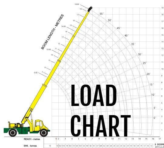

The measurements going up the right side of the chart note the boom length (in feet) at various levels of extension. How to Read a Crane’s Working Range Diagram To understand what the load radius is, let’s look at the working range diagram that accompanies the crane load chart. This is what’s known as the load/lift//boom/operating radius. This signifies that the figures in the left column refer to the horizontal distance from the center pin to the end of the boom. Looking back at the load chart, you should see another icon ( ) just above the left column of the chart. And it’s essential that you only reference the chart that matches the parameters of your lift. Many cranes will have multiple load charts to cover all possible configurations. The information in this load chart is only accurate when the crane is configured to meet all of these conditions. The chart only applies to lifts with all outriggers fully deployed, creating a 22’ 6” base for the crane.įigures are based on lifts where the cab can rotate 360°, as opposed to “over rear” lifts. The chart is based on lifts that use 11,608 lbs of counterweights. The chart provides information about lifts when the boom length ranges from 33’ to 105.’ This means it covers the full extension of the boom but does not have information about load capacities with a jib attached. Each signifies a specific piece of information about how the crane must be configured for the figures of the chart to be accurate. Let’s look at a load chart for the Grove RT650E as an example: But they should all include the same basic information. But knowing how to read crane load charts is still essential when working with cranes.Įvery manufacturer’s crane load charts will look a little different. And load indicators in the cabs signify when lifts approach or exceed a crane’s capacity.

Most lifts are planned using computer simulations these days. Understanding how to read a crane load chart allows you to calculate the crane’s load capacity as it relates to the boom angle and length.


 0 kommentar(er)
